Shadow Move Rendering in Killer Instinct: Season 3
A few things have happened lately that have given me the blog itch: I'm stir crazy from the COVID19 pandemic, new consoles are getting announced, a rejected GDC proposal of mine from several years back is fading in relevancy, the Killer Instinct documentary came out, and most importantly there were some interesting Tweets that made me nostalgic.
This really cool effect came to my attention from another tweet that links to some interesting pages by Hugo Elias.
If you are familiar with Killer Instinct on Xbox One, this might remind you of the Shadow Move effects from Season 1+2! And if you know me at all - you might know that I was responsible for maintaining and expanding the renderer for KI when Iron Galaxy became the developer for Seasons 2+3. The first season was developed by Double Helix Games, but they got purchased by Amazon Game Studios at the end of the season, causing Microsoft to have Iron Galaxy come on as a new development partner. I mention all this history because this blog post is going to detail how the Shadow Move effect was revamped for Season 3, but the original effect was developed by engineers+artists at Double Helix and credit goes to them for the great work there. Here is a clip I grabbed from this video of Aria showing off this original effect:

This effect is created almost exactly like the smokey hand shown off by SoerbGames in the tweets. There are two full screen buffers allocated and each frame a simulation step is run that ping pongs between the two in a manner similar to the "feedback" post by Hugo Elias. Each frame, the alpha of each pixel is decreased which causes any color data to fade out over time. However, the warping step is slightly more specific to KI. A reprojection is done to account for camera motion from frame to frame, as this is an in-world effect being simulated in a screen space buffer. In this version I believe this was done with an approximation that avoided a full matrix multiply, but I later changed this to do the full multiply (see this GPU Gems 3 article for details on how to do a reprojection) with the assumption the effect was happening within the plane the characters walk along in the game world. Doing this fixed some issues with drift of the effect that could occur when the camera panned as opposed to the purely translational motion it does most of the time. You can also see in the above clip that there is the inherent limitation that the shadow effect does not persist when off screen do to this being a screenspace simulation. The other primary warping is a 2D flow map texture that is tiled in screenspace used to warp the UV selection after reprojection, which gives the effect its smokey appearance as the texels are distorted over time.
Each frame, the result of the simulation is alpha composited with the scene color buffer after the environment is rendered but before characters are rendered. KI has a pretty hard split between rendering of characters and environments. There are environment particles and UI elements rendered before characters that the shadow moves and characters will then render on top of, and then another round of particle + UI rendering for anything that needs to be rendered in front of the characters. This rigid control is convenient within the constraints of a fighting game where the players are always walking along a fixed plane in the foreground. After the shadow moves composite, characters are rendered on top of them and can optionally inject their color data into the shadow move buffer with an opacity of 1 using MRT. This is done at artist controlled frequencies which you can observe by the strobing nature of Aria's shadow moves when she leaps forward. This lets the effect have a little more time to “breathe” before more color data is injected.
Season 3 Remix
So what about Season 3? We wanted to make a few changes. We did a big overhaul of environment lighting and wanted to make some changes to characters to go along with this. Our art director didn't love the injection of character color directly into the effect - which can add a lot of variability to how the effect looks depending on the color palette and lighting of the character itself. We also wanted some more interesting motion in the flow of the effect as well - optimizations from throughout Season 2 and moving the effect to run in async compute opened up some more budget to do more than a single flow map sample. I joked a few times: "imagine what we could do with *two* texture samples." Here's Aria again with the Season 3 version of the effect taken from this video compilation:
There are a few differences here. Obviously, it's a consistent purple color now, with the character’s materials tinting purple when it is active as well. But if that's all we did, I wouldn't be writing this blog post :) We did want a consistent color across all moves and characters, but we also wanted a more inky and spiraling motion to the effect. Initial attempts to update the motion looked into compositing a large number of octaves of white noise. This produced some interesting effects but ultimately suffered from both being too expensive (too many texture samples to look good) and being too counter-intuitive for the effects artists to tune in any meaningful way. I unfortunately do not have any WIP videos from this period.
These investigations lead me to start looking a new approach that would hopefully be more efficient and easier to tune. I had first heard about "curl noise" when Bill Rockenbeck from Sucker Punch presented their GPU particle architecture at GDC and mentioned curl noise specifically as being a critical element of the look of a lot of their effects. When following up on this, I found this paper, "Curl-Noise for Procedural Fluid Flow," by Robert Bridson et al (who is a bit of an expert in the field of fluid simulation) to be an incredibly easy and compelling read. Bridson's work turns any potential field (e.g. a single channel noise texture) into a 2 channel flow map that results in incompressible flow. This leads to much more believable results at minimal cost.
Applying the curl operator to a noise function simply requires the partial derivatives in X and Y at each location. The curl is then simply:
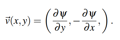
Curl = (Partial Derivative in Y, Negative of Partial Derivative in X)
The partial derivatives are just the rate of change in each direction separately. You might be able to derive these from your noise analytically if you can calculate the derivatives for it directly, however I stuck with just computing the finite differences at each texel to allow an arbitrary input texture to be used. My initial version simply used the immediate neighbors, but I did change it to using a “5-point stencil” at the cost of 2 more samples in each direction, which seemed to yield slightly better results at the time. In hindsight, I wish I had spent some more time evaluating the quality of different approaches here and if it really mattered much on the final results. To help visualize what is going on here, here is a tiling simplex noise texture:

And here is what happens when you calculate the Curl at each texel using a 5-point stencil:

This created some really cool effects right away. In fact, an amusing detail in my initial tests of just calculating the curl of an arbitrary input texture that did not correctly tile was that the shadow moves would flow along the hard edge of the texture boundary. This wasn’t what I wanted, but it gave me confidence that the artists would be able to do something cool with it.
One thing that I did need to address still was that the flow was really obviously static. It’s not interesting to see the effect flowing into the same swirls in screen space each frame. There is a really easy solution here explained by Bridson’s paper. The input can be modulated in any way, and the resulting Curl will still be an incompressible flow. This means that the Curl can’t be computed offline, but I only needed to process it for a small texture when relying on tiling noise. For KI, each frame I simply lerp back and forth over time between the noise texture and the same noise texture offset by 0.5 in both U and V. I added support for art to set each texture separately, but the results were good enough that they only needed to adjust the speed at which the lerp occurred.
Shader Toy Example
I’ve put together a shader toy to show this off - and honestly this is the most I’ve ever done with shader toy and I possibly had too much fun with this. I’ve extracted a couple of clips for viewing on the blog without running it, but you can view the whole thing here:
https://www.shadertoy.com/view/Wl2cW1
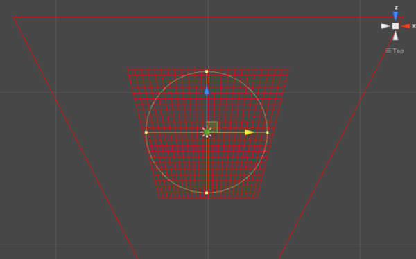
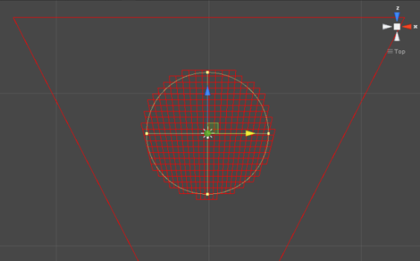
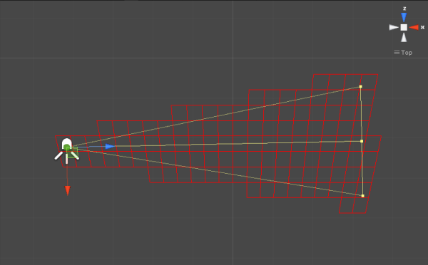
First, I have an example of a tiling noise texture being generated and a visualization of the flow vectors created from it. The tiling noise is created by mapping UV space to a torus in a 3D noise field - since the torus wraps around in all 4 directions it will tile naturally. We generated the noise textures for Killer Instinct this way in an offline process. As mentioned before, I offset the noise and lerp back and forth between the original and the offset to make the flow more dynamic over time.
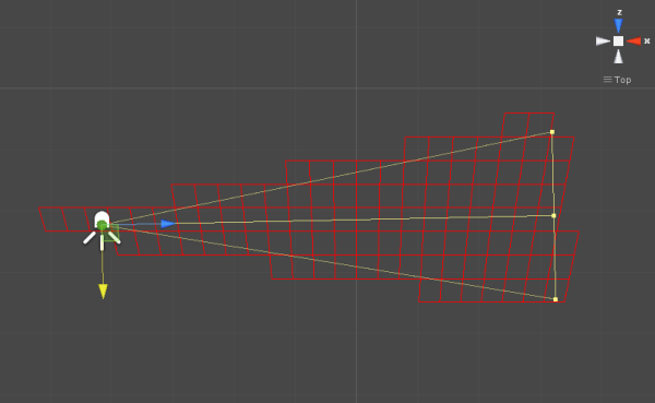
I’ve taken this example of how to calculate the flow and applied it to a one of the green screen videos that is included in shader toy. This ends up being very similar to the original shadow move effect augmented with curl noise (and without any 3D camera reprojection).

I’ve credited two other shader toys that I cribbed code from for generating the input noise and removing the green screen from the video in the relevant sections. I should mention some interesting ways that the effect can be tuned without modifying the original noise input directly. First, if you multiply the noise values by a constant before computing the curl, it effectively heightens or smooths the slopes in the field, which in turn make the simulation either more or less swirly. If you introduce a multiplier to the flow vectors after they have been calculated, that will instead change how quickly the effect moves through the vector field. Finally, there are controls for how often to inject new data into simulation and how quickly the opacity should decay causing the effect to fade out.
Rendering the Effect
While this yielded some really interesting results right away, there are a number of additional details to creating the aesthetics of the final effect specific to Killer Instinct. First and foremost, because we are no longer using the lit character color as an input of the simulation and want some sort of purple-ish effect, we are no longer tied down to using MRT during character shading to inject the shadow move simulation. Instead, we run a separate character rendering pass on injection frames that render with geometry inflated along the normal vector into what we would call the “blob buffer” because it had blobby characters and creates the main volume of the effect. Inflating the characters gave the effect a lot more volume right away as the effect was running. Here is what the blob buffer looks like simulating for a frame and then just a shot of the character being injected without more warping applied:
This buffer has 4 components. The red channel is the age of the texel, which is for most purposes just the opacity, but the effects artists had full control here for how it was interpreted in the apply step, so they can do things like alter the color of the effect over time. As before, this is ticked down with each frame of the simulation.

Age (R)
The green and blue channels hold a distortion vector used to create a refractive effect in parts of the effect. This ended up being very subtle in the end with everything else going on during shadow moves at the same time, but I wasn’t going to fight the artists on using it because it was ultimately cheap to include.

Distortion Vector (GB)
The alpha channel holds what we called “Focus” which is really just a gradient originating from a particular point on the character’s body. This gradient is the important part for deciding the main coloration of the effect. This was hooked up to a color ramp in the apply step that I’ve included immediately after the Focus buffer here.

Focus (A)

This color ramp is actually 2 ramps stacked together… because the second part of it is used on what we call the “wisp buffer.” The wisp buffer is probably the most logical conclusion to me joking that we could afford two texture samples per pixel instead of just one. To get some more variety and lingering effects, we actually run two shadow move simulations every frame with separate data. This is also pretty subtle, but becomes most obvious when the blob buffer is aging out and the wisps are lingering longer. They also sometimes break off a bit more on their own. The wisps are just screen-space trail renderers attached to key bones of the characters.
Wisp Buffer + Injection
This is a two channel RG buffer, where the red channel holds an age value just like with the blob buffer, and the green channel holds an opacity value, which comes from a texture provided by art that tiles horizontally. Opacity and age are combined together to determine the blend with the scene color as well as the look-up into the color ramp. We could’ve made this more complicated/flexible with more data, but this is all art really needed for our purposes.
Finally, as mentioned earlier, the effect gets composted into the scene color before the forward lighting render of the characters. Here’s a still of this in action, including a good shot of some refraction happening in the lower half of the effect:

Performance
*Rubs temples* If you’ve read this far, you might wonder what time this ran in on Xbox One. I unfortunately don’t have access to a running build of Killer Instinct or any archived PIX captures of the effect as far as I can find and it’s been too many years for me to have specifics. The short answer is “reasonably fast” - Killer Instinct keeps a solid 60 FPS on Xbox One at a resolution of 1600x900, which is also the resolution of the blob and wisp buffers. The flow map update is quite small at just 256x256 pixels. Running synchronously, I believe this took ~0.75 ms total, but don’t take my word for it at this point.
As I mentioned before - I ran it in async compute on top of our prepass because it had minimal data dependencies to current frame data. Killer Instinct uses clustered forward shading, and we had a pretty extensive prepass to minimize overshading during lighting and it resulted in a nice chunk of time to overlap with other work. Furthermore, the first step of updating the the flow vectors didn’t need to wait for the next frame’s camera data to be available so it would get kicked right away on the previous frame to overlap with any inter-frame bubbles when work was not kicked right away from the CPU.
Final Thoughts
Overall, I'm pretty happy with how this turned out. There are some things I’ve wondered about for potential improvements that I never got to at the time. The biggest artifact with the version that shipped is a rippled aliasing whenever really tight swirls occur in the motion. I have a few theories for why this aliasing occurs: my main thought is that there is a limited amount of data being stored in the buffer from frame to frame and as the warping becomes tightly compacted, some data disappears entirely. If we were doing something like simulating a particle system where each particle sampled the vector field to determine its motion, no particles would be lost. As I mentioned before, I also never really got the chance to fully evaluate if my curl vectors were really generated and sampled in the highest quality way from start to finish. Finally, I would point out that I now know a lot more about reprojection diffusion from working on games with temporal anti-aliasing. I bet the legacy version of the effect in particular might have benefited from bicubic filtering, even if diffusion fits with the overall look of a smoky effect.
I hope you enjoyed reading about this! I should credit two of my colleagues from IGS that worked with me on shadow move rendering: Bert Wierenga for early investigations into the Season 3 changes and Rogier Van Etten as the primary effects artist that collaborated with us. Writing this has made me very nostalgic for working on Killer Instinct - I learned a lot from working on that game. Maybe I will feel inspired to find some more time to write-up what else I’ve gotten up to in the past 5 years with computer graphics. If you have thoughts or questions, feel free to leave comments, pester me on Twitter, or e-mail me directly.